
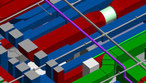



If you have ever worked on a construction site where a conduit run had to be torn out because it collided with a duct, you already know why electrical BIM services exist. These services help teams catch that kind of problem on a screen, weeks before it becomes a costly mess on site.
In this article, we will walk through what electrical BIM modeling actually is, how it works, and how it helps electrical, mechanical, and plumbing teams work from one coordinated model instead of a stack of separate drawings.
What is BIM Electrical Modeling?
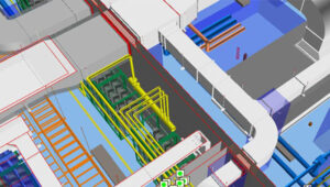
BIM electrical modeling is the process of building a detailed, data-rich 3D representation of a building’s electrical systems, such as panels, conduits, cable trays, lighting, switchgear, and more, inside a shared digital model.
Instead of a flat drawing, you get an object that carries real information: size, load, manufacturer, and location.
The Shift from 2D Schematics to 3D Digital Models
For decades, electrical layouts lived on 2D schematics. Engineers relied on experience and careful cross-checking to imagine how a wall-mounted panel might sit next to a structural beam or a plumbing line.
That guesswork is exactly where clashes started. A 3D model built by electrical BIM services in Australia removes the guesswork because every element occupies real, measurable space, and every trade can see it.
Key Equipment Built into Electrical BIM Models
A typical electrical BIM model includes transformers, distribution boards, cable trays, conduits, light fixtures, fire alarm devices, and low-voltage systems. Each piece is modeled with its true dimensions and clearance requirements, so nothing is left to assumption.
How Level of Development (LOD) Enhances Accuracy
Level of Development, or LOD, defines how much detail a model element carries at each project stage. Early on, a panel might just be a placeholder box (LOD 200). By construction stage, that same panel is modeled with exact dimensions, connections, and manufacturer data (LOD 400). Higher LOD means fewer surprises during installation.
Across the projects we have modeled in our electrical CAD drafting services, the pattern is consistent: a model rushed to LOD 200 and left there tends to surface its clashes on site, not on screen. Pushing detail up early, well before construction drawings are due, is what actually prevents rework later.
How Does BIM Electrical Modeling Work?
Step 1: Integrating Data and Technical Specs
The process starts by feeding in load calculations, panel schedules, and manufacturer cut sheets, so the model reflects real equipment rather than generic shapes.
Step 2: Aligning Layouts with Architectural Models
Electrical layouts are then aligned against the architectural and structural models, so routing decisions respect walls, ceilings, and beams from day one.
Step 3: Using Automation for Quick Route Adjustments
Modern BIM electrical modeling tools allow automated routing of conduits and cable trays, so when a wall shifts or a ceiling height changes, the electrical layout can adjust in minutes instead of days.
Step 4: Validating Designs Against Electrical Codes
Before anything moves to construction, the model built using electrical CAD drafting services is checked against local and national electrical codes to confirm clearances, circuit loading, and equipment placement are compliant.
This step matters because a clash-free model that ignores code requirements, like panel clearances under AS/NZS wiring rules in Australia or the NEC elsewhere, is not actually a usable model. As the provider of the best electrical BIM services in Australia, we understand that code validation is what keeps a model trustworthy, not just tidy.
Traditional MEP Coordination vs. BIM Electrical Modeling
The Old Way: 2D CAD Overlays and Manual Errors
Traditional coordination meant printing out overlays from different trades and holding them up to the light, hoping to spot overlaps. It used to work, but sometimes it was slow and left plenty of room for human error.
The BIM Approach: Automated 3D Coordination
With a federated 3D model, every trade’s design sits in one coordinated environment. Clashes that once needed a trained eye to spot are now flagged automatically by the software.
How Digital Models Shorten Project Timelines
Because problems are found and fixed digitally, fewer change orders reach the site. That alone shortens timelines and reduces the back-and-forth between contractors and designers.
How Electrical BIM Services Prevent Common On-Site Clashes
Stopping Physical Hard Clashes Before Installation
A hard clash is a straightforward physical overlap, like a cable tray running straight through a structural beam. The best electrical BIM services catch these clashes long before construction, saving the cost of rework.
Managing Soft Clashes for Maintenance Clearances
Soft clashes are trickier. A panel might technically fit next to a duct, but there is no room left for a technician to open the panel door for maintenance. Electrical BIM services flag these clearance issues too, not just physical overlaps.
Resolving 4D Scheduling and Trade Sequence Conflicts
Some clashes are not about space at all. They are about timing. 4D BIM adds a schedule dimension, so teams can see if the electrical crew and the plumbing crew are both scheduled to work in the same ceiling void on the same day.
The ROI of Professional Electrical BIM Services
Fewer site clashes mean fewer delays, less wasted material, and lower labor costs from rework. Professional electrical BIM services pay for themselves many times over across the life of a project.
Step-by-Step Workflow for Clash-Free MEP Coordination
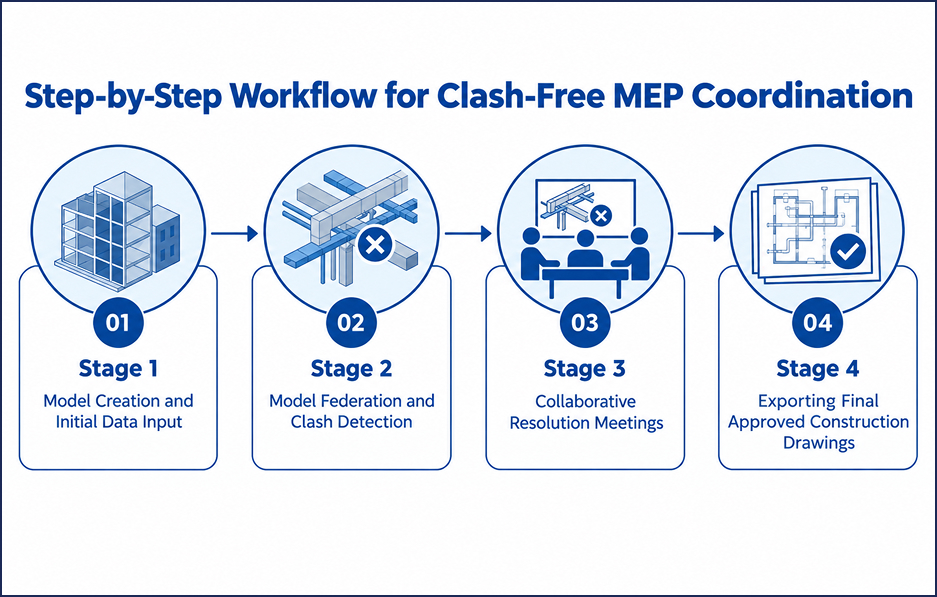
Stage 1: Model Creation and Initial Data Input
The electrical team builds out the model using project specifications, equipment schedules, and code requirements as the foundation.
Stage 2: Model Federation and Clash Detection
The electrical model is combined, or “federated,” with architectural, structural, and other MEP models, and clash detection software runs a full scan for overlaps.
Stage 3: Collaborative Resolution Meetings
Teams meet, often weekly, to review flagged clashes together and agree on fixes before anyone touches a tool on site.
Stage 4: Exporting Final Approved Construction Drawings
Once the model is clash-free, final construction drawings and shop drawings are exported directly from it, keeping everything consistent with what gets built.
How SmartCADD Delivers Precise Electrical BIM Services for Seamless MEP Coordination
At SmartCADD, we provide the best electrical BIM services in Australia, along with mechanical and plumbing BIM support, for architects, engineers, and contractors who need coordinated, buildable models.
Why Choose SmartCADD for Electrical BIM Services?
We combine experienced modelers with strict quality checks, so every electrical BIM model we deliver has already been reviewed for clashes, code compliance, and constructability before it reaches your desk.
Every model passes through an internal review before it goes out, checked against the project’s own specifications and applicable codes, not just against other trade models. That extra layer is what our clients rely on when they sign off on a set of drawings.
Our Proven Approach to BIM Electrical Modeling
Our workflow follows the same clash-detection and federation process outlined above, backed by our electrical CAD drafting services for teams that need supporting 2D documentation alongside the 3D model.
Key Business Benefits of Partnering with SmartCADD

Working with us means fewer surprises on site, faster approvals, and construction documents your teams can trust from the first day of installation.
Conclusion: The Future of Error-Free MEP Construction
Clash-free construction is no longer a nice-to-have; it is becoming the standard expectation on modern projects. As buildings get more complex, electrical BIM services will keep playing a bigger role in keeping MEP coordination accurate, efficient, and free of costly on-site surprises.
